
The Basics
After writing the first blinky program using random delay , now its time to improvise and induce precise delay using timers! The real fun in embedded starts when you start playing with timers (& UARTs , PWM , etc..). I’ll try to keep it simple and short so its easy to understand.
LPC2148 comes loaded with two 32-bit-Timer blocks. Each Timer block can be used as a ‘Timer’ (like for e.g. triggering an interrupt every ‘t’ microseconds) or as a ‘Counter’ and can be also used to demodulate PWM signals given as input.
A timer has a Timer Counter(TC) and Prescale Register(PR) associated with it. When Timer is Reset and Enabled TC is set to 0 and incremented by 1 every ‘PR+1’ clock cycles. When it reaches its maximum value it gets reset to 0 and hence restarts counting. Prescale Register is used to define the resolution of the timer. If PR=0 then TC is incremented every 1 clock cycle of the peripheral clock. If PR=1 then TC is incremented every 2 clock cycles of peripheral clock and so on. By setting an appropriate value in PR we can make timer increment or count : every peripheral clock cycle or 1 microsecond or 1 millisecond or 1 second and so on.
Each Timer has four 32-bit Match Registers and four 32-bit Capture Registers.
The Register Specifics
What is a Match Register anyways ?
Ans: A Match Register is a Register which contains a specific value set by the user. When the Timer starts – every time after TC is incremented the value in TC is compared with match register. If it matches then it can Reset the Timer or can generate an interrupt as defined by the user. We are only concerned with match registers in this tutorial.
- Stop Timer on Match(i.e when the value in count register is same as than in Match register) and trigger an optional interrupt.
- Reset Timer on Match and trigger an optional interrupt.
- To count continuously and trigger an interrupt on match.
What are Capture Registers ?
Ans: As the name suggests it is used to Capture Input signal. When a transition event occurs on a Capture pin , it can be used to copy the value of TC into any of the 4 Capture Register or to genreate an Interrupt. Hence these can be also used to demodulated PWM signals. We are not going to use them in this tutorial since we are only concerned with using Timer block as a ‘Timer’. We’ll see them in upcoming tutorial since it needs a dedicated tutorial.
1) PR : Prescale Register (32 bit) – Stores the maximum value of Prescale counter after which it is reset.
2) PC : Prescale Counter Register (32 bit) – This register increments on every PCLK(Peripheral clock). This register controls the resolution of the timer. When PC reaches the value in PR , PC is reset back to 0 and Timer Counter is incremented by 1. Hence if PR=0 then Timer Counter Increments on every 1 PCLK. If PR=9 then Timer Counter Increments on every 10th cycle of PCLK. Hence by selecting an appropriate prescale value we can control the resolution of the timer.
3) TC : Timer Counter Register (32 bit) – This is the main counting register. Timer Counter increments when PC reaches its maximum value as specified by PR. If timer is not reset explicitly(directly) or by using an interrupt then it will act as a free running counter which resets back to zero when it reaches its maximum value which is 0xFFFFFFFF.
4) TCR : Timer Control Register – This register is used to enable , disable and reset TC. When bit0 is 1 timer is enabled and when 0 it is disabled. When bit1 is set to 1 TC and PC are set to zero together in sync on the next positive edge of PCLK. Rest of the bits of TCR are reserved.
5) CTCR : Count Control register – Used to select Timer/Counter Mode. For our purpose we are always gonna use this in Timer Mode. When the value of the CTCR is set to 0x0 Timer Mode is selected.
6) MCR : Match Control register – This register is used to control which all operations can be done when the value in MR matches the value in TC. Bits 0,1,2 are for MR0 , Bits 3,4,5 for MR1 and so on.. Heres a quick table which shows the usage:
Bit 0 : Interrupt on MR0 i.e trigger an interrupt when MR0 matches TC. Interrupts are enabled when set to 1 and disabled when set to 0.
Bit 1 : Reset on MR0. When set to 1 , TC will be reset when it matched MR0. Disabled when set to 0.
Bit 2 : Stop on MR0. When set to 1 , TC & PC will stop when MR0 matches TC.
Similarly bits 3-5 , 6-8 , 9-11 are for MR1 , MR2 , MR3 respectively.
7) IR : Interrupt Register – It contains the interrupt flags for 4 match and 4 capture interrupts. Bit0 to bit3 are for MR0 to MR3 interrupts respectively. And similarly the next 4 for CR0-3 interrupts. when an interrupt is raised the corresponding bit in IR will be set to 1 and 0 otherwise. Writing a 1 to the corresponding bit location will reset the interrupt – which is used to acknowledge the completion of the corresponding ISR execution.
Setting up & configuring Timers in LPC2148
To use timers we need to first configure them. We need to set appropriate values in TxCTCR , TxIR , TxPR and reset TxPC , TxTC. Finally we assign TxTCR = 0x01 which enables the timer.
- Set appropriate value in TxCTCR
- Define the Prescale value in TxPR
- Set Value(s) in Match Register(s) if required
- Set appropriate value in TxMCR if using Match registers / Interrupts
- Reset Timer – Which resets PR and TC
- Set TxTCR to 0x01 to Enable the Timer when required
- Reset TxTCR to 0x00 to Disable the Timer when required
Now lets implement to basic function required for Timer Operation:
1. void initTimer0(void);
2. void delayMS(unsigned int milliseconds);
#1) initTimer0(void); [Used in Example #1]
void initTimer0(void)
{
	/*Assuming that PLL0 has been setup with CCLK = 60Mhz and PCLK also = 60Mhz.*/

	T0CTCR = 0x0;
	T0PR = PRESCALE-1; //(Value in Decimal!) - Increment T0TC at every 60000 clock cycles
	//Count begins from zero hence subtracting 1
	//60000 clock cycles @60Mhz = 1 mS

	T0TCR = 0x02; //Reset Timer
}
Prescale (TxPR) Related Calculations:
The delay or time required for 1 clock cycle at ‘X’ MHz is given by :

Hence in our case when PR=0 i.e TC increments at every PCLK the delay required for TC to increment by 1 is:

Similarly when we set PR = 59999 the delay in this case will be:
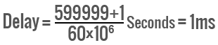
… which boils down to 1/1000 = 0.001 Seconds which is nothing but 1 Milli-Second i.e mS. Hence the delay required for TC to increment by 1 will be 1mS.
#2) delayMS(unsigned int milliseconds);
void delayMS(unsigned int milliseconds) //Using Timer0
{
	T0TCR = 0x02; //Reset Timer

	T0TCR = 0x01; //Enable timer

	while(T0TC < milliseconds); //wait until timer counter reaches the desired delay

	T0TCR = 0x00; //Disable timer
}
Real World LPC2148 Timer Examples with sample code
Example #1) - Basic Blinky example using Timer
Now lets make a blinky program which flashes a LED every half a second. Since 0.5 second = 500 millisecond we will invoke 'delayMS' as delayMS(500).
/*(C) Umang Gajera - www.ocfreaks.com
More Embedded tutorials @ www.ocfreaks.com/cat/embedded/
LPC2148 Basic Timer example.
License : GPL.*/
#include <lpc214x.h>

#define PLOCK 0x00000400
#define PRESCALE 60000   //60000 PCLK clock cycles to increment TC by 1

void delayMS(unsigned int milliseconds);
void initClocks(void);
void initTimer0(void);
void setupPLL0(void);
void feedSeq(void);
void connectPLL0(void);

int main(void)
{
	initClocks(); //Initialize CPU and Peripheral Clocks @ 60Mhz
	initTimer0(); //Initialize Timer0
	IO0DIR = 0xFFFFFFFF; //Configure all pins on Port 0 as Output

	while(1)
	{
		IO0SET = 0xFFFFFFFF; //Turn on LEDs
		delayMS(500); //0.5 Second(s) Delay
		IO0CLR = 0xFFFFFFFF; //Turn them off
		delayMS(500);
	}
	//return 0; //normally this wont execute ever
}

void initTimer0(void)
{
	/*Assuming that PLL0 has been setup with CCLK = 60Mhz and PCLK also = 60Mhz.*/

	T0CTCR = 0x0;
	T0PR = PRESCALE-1; //(Value in Decimal!) - Increment T0TC at every 60000 clock cycles
	//Count begins from zero hence subtracting 1
	//60000 clock cycles @60Mhz = 1 mS

	T0TCR = 0x02; //Reset Timer
}

void delayMS(unsigned int milliseconds) //Using Timer0
{
	T0TCR = 0x02; //Reset Timer

	T0TCR = 0x01; //Enable timer

	while(T0TC < milliseconds); //wait until timer counter reaches the desired delay

	T0TCR = 0x00; //Disable timer
}

void initClocks(void)
{
    setupPLL0();
    feedSeq(); //sequence for locking PLL to desired freq.
    connectPLL0();
    feedSeq(); //sequence for connecting the PLL as system clock

    //SysClock is now ticking @ 60Mhz!

    VPBDIV = 0x01; // PCLK is same as CCLK i.e 60Mhz

    //Using PLL settings as shown in : http://www.ocfreaks.com/lpc214x-pll-tutorial-for-cpu-and-peripheral-clock/
    //PLL0 Now configured!
}


//---------PLL Related Functions :---------------

//Using PLL settings as shown in : http://www.ocfreaks.com/lpc214x-pll-tutorial-for-cpu-and-peripheral-clock/

void setupPLL0(void)
{
	//Note : Assuming 12Mhz Xtal is connected to LPC2148.

	PLL0CON = 0x01; // PPLE=1 & PPLC=0 so it will be enabled
					// but not connected after FEED sequence

	PLL0CFG = 0x24; // set the multipler to 5 (i.e actually 4)
					// i.e 12x5 = 60 Mhz (M - 1 = 4)!!!
					// Set P=2 since we want FCCO in range!!!
					// So , Assign PSEL =01 in PLL0CFG as per the table.
}

void feedSeq(void)
{
	PLL0FEED = 0xAA;
	PLL0FEED = 0x55;
}

void connectPLL0(void)
{
	// check whether PLL has locked on to the  desired freq by reading the lock bit
	// in the PPL0STAT register

	while( !( PLL0STAT & PLOCK ));

	// now enable(again) and connect
	PLL0CON = 0x03;
}
Example #2) - Blinky example using Timer with Interrupt
Also if you are using Keil Version4(or higher) you'll need to edit Target Option settings and those Crossworks for ARM etc .. you need to manually enable global interrupts - A simple way to make interrupts working is @ Here
/*(C) Umang Gajera - www.ocfreaks.com
More Embedded tutorials @ www.ocfreaks.com/cat/embedded/
LPC2148 Timer example using Interrupt.
License : GPL.*/

#include <lpc214x.h>

#define PLOCK 0x00000400
#define MR0I (1<<0) //Interrupt When TC matches MR0
#define MR0R (1<<1)	//Reset TC when TC matches MR0

#define DELAY_MS 500 //0.5 Seconds Delay
#define PRESCALE 60000 //60000 PCLK clock cycles to increment TC by 1

void delayMS(unsigned int milliseconds);
void initClocks(void);
void initTimer0(void);
__irq void T0ISR(void);

void setupPLL0(void);
void feedSeq(void);
void connectPLL0(void);


int main(void)
{
	initClocks(); //Initialize CPU and Peripheral Clocks @ 60Mhz
	initTimer0(); //Initialize Timer0

	IO0DIR = 0xFFFFFFFF; //Configure all pins on Port 0 as Output
	IO0PIN = 0xF;

	T0TCR = 0x01; //Enable timer

	while(1); //Infinite Idle Loop

	//return 0; //normally this wont execute ever
}

void initTimer0(void)
{
	/*Assuming that PLL0 has been setup with CCLK = 60Mhz and PCLK also = 60Mhz.*/

	//----------Configure Timer0-------------

	T0CTCR = 0x0;

	T0PR = PRESCALE-1; //(Value in Decimal!) - Increment T0TC at every 60000 clock cycles
	//Count begins from zero hence subtracting 1
	//60000 clock cycles @60Mhz = 1 mS

	T0MR0 = DELAY_MS-1; //(Value in Decimal!) Zero Indexed Count - hence subtracting 1

	T0MCR = MR0I | MR0R; //Set bit0 & bit1 to High which is to : Interrupt & Reset TC on MR0

	//----------Setup Timer0 Interrupt-------------

	VICVectAddr4 = (unsigned )T0ISR; //Pointer Interrupt Function (ISR)

	VICVectCntl4 = 0x20 | 4; //0x20 (i.e bit5 = 1) -> to enable Vectored IRQ slot
	//0x4 (bit[4:0]) -> this the source number - here its timer0 which has VIC channel mask # as 4
	//You can get the VIC Channel number from Lpc214x manual R2 - pg 58 / sec 5.5

	VICIntEnable = 0x10; //Enable timer0 int

	T0TCR = 0x02; //Reset Timer
}

__irq void T0ISR(void)
{
	long int regVal;
	regVal = T0IR; //Read current IR value

	IO0PIN = ~IO0PIN; //Toggle the state of the Pins

	T0IR = regVal; //Write back to IR to clear Interrupt Flag
	VICVectAddr = 0x0; //This is to signal end of interrupt execution
}

void initClocks(void)
{
	setupPLL0();
	feedSeq(); //sequence for locking PLL to desired freq.
	connectPLL0();
	feedSeq(); //sequence for connecting the PLL as system clock

	//SysClock is now ticking @ 60Mhz!

	VPBDIV = 0x01; // PCLK is same as CCLK i.e 60Mhz

	//PLL0 Now configured!
}

//---------PLL Related Functions :---------------

//Using PLL settings as shown in : http://www.ocfreaks.com/lpc214x-pll-tutorial-for-cpu-and-peripheral-clock/

void setupPLL0(void)
{
	//Note : Assuming 12Mhz Xtal is connected to LPC2148.

	PLL0CON = 0x01; // PPLE=1 & PPLC=0 so it will be enabled
					// but not connected after FEED sequence

	PLL0CFG = 0x24; // set the multipler to 5 (i.e actually 4)
					// i.e 12x5 = 60 Mhz (M - 1 = 4)!!!
					// Set P=2 since we want FCCO in range!!!
					// So , Assign PSEL =01 in PLL0CFG as per the table.
}

void feedSeq(void)
{
	PLL0FEED = 0xAA;
	PLL0FEED = 0x55;
}

void connectPLL0(void)
{
	// check whether PLL has locked on to the  desired freq by reading the lock bit
	// in the PPL0STAT register

	while( !( PLL0STAT & PLOCK ));

	// now enable(again) and connect
	PLL0CON = 0x03;
}